As mentioned in the previous post, I decided to write a program (translation: modify an existing program) to make it a little easier to enter models (at least not needing to type them in!). You can find my first attempt at:
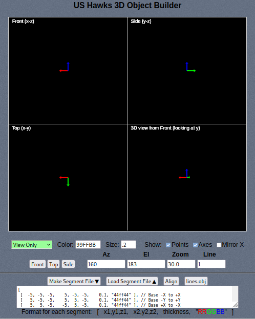
https://ushawks.org/designer/object_builder.htmThat program has a lot of "clunkiness" (and probably a few bugs), but it mostly works, and it might help anyone looking for a quick way to sketch something in 3D without downloading anything or even learning too much. Here's what it basically looks like:

- 3D_Object_Builder_67pct.png (105.74 KiB) Viewed 1219 times
General DescriptionThere are 4 viewing panels at the top. The upper left shows a view from the front (looking at the x-z plane along the y axis). The upper right shows a view from the right side (looking at the y-z plane along the x axis). The lower left shows a view from the top (looking down at the x-y plane along the z axis). And finally, the lower right shows the 3D view which can be rotated to any angle (using a pitch/yaw interaction). The model can be edited by adding, moving, and removing points and lines in the first 3 viewing panels (x-y, x-z, y-z). No editing can be done in the 3D window, and it is only for viewing.
There are currently 6 modes of operation: View Only, Add Points, Add Lines, Move Points, Delete Points, and Delete Lines. These are all selected by the drop down box that starts out as "View Only" (light green).
The basic idea is that you start by adding points, then connect the points to make the line segments that define the drawing (essentially a mesh of points and line segments). Once the line segments are connected to points, moving the points will move the line segments.
As you create each line segment, ("Add Line"), the new line will be drawn with the color and size specified by the "Color" and "Size" boxes. The color is the typical red, green, blue specified in hex. Each hex digit can go from 0 to F, and each color has 2 digits. So full red would be FF0000. The two "F" values specify the red. The next two zeros are the green, and the last two are the blue. The size value is somewhat relative. In most cases, a small value (less than 1) is best, and you can experiment with it to see what looks best. While you can easily move the lines by moving the points, you cannot easily change any other line attributes (like color or thickness). To change color or thickness, you will have to delete the line segment, change the color and thickness values, and then recreate the line. You can also change these (and any other values) by manually editing the segments file described below.
To the right of the Size box are 3 viewing settings to show Points, show Axes, and show with X Mirrored. The "Show Points" just shows or hides the little round circles at each point. The "Show Axes" shows or hides the small set of axes at the origin (red=x, green=y, and blue=z). The "Mirror X" is handy for making symmetrical objects because you only have to add points and lines on one half of the model, and the program will duplicate them on the opposite side of the y-z plane (along the x axis). This is especially handy for making hang gliders!
The second row of buttons and fields control the viewing. There are buttons to view from the Front, Top, and Side. There are also Az, El, and Zoom fields that can be entered for a specific view. There's also a Line thickness field which will increase or decrease the line thickness for all lines in the view.
The third row of buttons are related to the segment definitions that make up the model. The segments are shown in the text box below that row of buttons. The segments represent the model, and if you want to save a model, just copy that text and paste it into any application that lets you save and open it again.
The segment file format is very simple. Each segment line consists of two points where each point has an x, y, and z value. So 2 points is 6 values. Each line also has its own "thickness" (value 7) and color (value 8). There's a quick reminder of this format below the text entry box for the segments. All values are separated by commas. Each line segment specification is enclosed in a pair square brackets ( [ ] ), and the whole list of line segments is also enclosed in a pair or square brackets ( [ ] ). There must also be a comma after the closing square bracket of each segment. This is compliant with the common
"JSON" format used in many other aspects of computer programming.
Modes of OperationHere are the details of each mode of operation:
- View Only - As implied, this mode doesn't let you do any screen editing. You can move the view in the 3D window by clicking and dragging. You can also change the model through the buttons, but not by clicking in the view panels. It's a good idea to be in this mode to keep from accidentally clicking and adding or deleting lines and points. There is no "undo" capability in this program!
- Add Points - This mode enables adding points by clicking in any of the 3 fixed windows (x-y, x-z, or y-z). Points cannot be added to the 3D view. When you click, a new point will be added and it will be visible in all 4 views.
- Add Lines - This mode enables adding lines by clicking on a start point and end point for each line. The points must already exist, and the program will choose the two points closest to where you clicked. There is no reminder of whether you've clicked or not, so it's easy to get confused. Be careful, and be sure to make 2 clicks (start and end) for each line segment. If you click twice and don't see any lines, check on the visibility (width and color) to be sure that the line will be thick and bright enough to see.
- Move Points - This mode enables moving existing points by clicking and dragging. As with all other editing modes, this does not work in the 3D viewing window, but the results can be seen in the 3D view. Just click each point, and drag it to a different location. All of the attached lines will follow.
- Delete Points - This mode enables deleting points by clicking on them. This will delete the nearest point to the location that was clicked - even if it is very far away. This makes it pretty easy to delete a lot of points by just rapidly clicking anywhere in the window. Any lines attached will also be deleted, so be careful.
- Delete Lines - This mode enables deleting lines without deleting points. Deleting a single line requires two mouse clicks - one on each end of the line. As with deleting points, the program will find the nearest points to each click - even if they are far away. So be careful.
Saving and LoadingThere is no "cloud storage" associated with this program. You have to save your own work by hand. This is done with the "Make Segment File" button that will copy all of your points and lines into a text box that you can use to copy into other storage locations (typically a text file on your computer). When you click the "Make Segment File" button, it will generate the segment file data in the text box. Similarly, you can restore the data to the drawing panels by clicking the "Load Segment File" button. It will read the text in the box and decode it into a drawing. Note that this can be used to temporarily store and restore your work. It's not quite as good as an "undo" button, but it's close. When you have something you like, just click the "Make Segment File" button, and it will hold a copy of that version. You can easily restore it with the "Load Segment File" button. But if you've done a lot of work, it's best to keep a copy somewhere else as well.
In addition to the "Make Segment File" and "Load Segment File" buttons, there are also "Align" and "lines.obj" buttons. The "Align" button simply aligns the columns in the list of segments to make them easier to read. The "lines.obj" button creates a pop-up dialog box with all of the points and lines represented in "OBJ" format. This is a fairly standard 3D drawing format, and it will allow you to import your work into other 3D drawing programs. However, the color and thickness of your lines is not stored in the .OBJ format, so don't use that as your only storage mechanism.
ExamplesThe last part of the page is for examples. These are best loaded by using the drop down selector and the "Load Selected Example" button. That procedure ensures that any additional viewing settings (scaling scaling and mirroring) are consistent with the example being loaded. Examples can also be loaded into the text area with the "Load" button beside each example. But the "Load" buttons may use the wrong display settings, so it's better to use the "Load Selected Example" button in most cases.
SharingOne of the nice features of this program is that you can easily share models just by copying the text and pasting it into a post here on U.S. Hawks or anywhere else. Just give a link to the program (
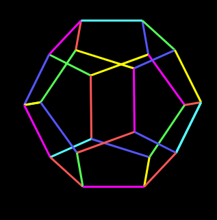
https://ushawks.org/designer/object_builder.htm) so people can find it and paste in your design. The format is actually a bit redundant (points are repeated), but it's easy to write without keeping track of indexes between points and lines as needed in other formats (like .OBJ). For example, here's a dodecahedron rendered in this program from the code in an earlier post to this topic:

- dodecahedron.png (17.19 KiB) Viewed 1219 times
Working Off-LineWhile this program is conveniently available on-line, note that it can also be used off-line by downloading the page to your local computer. Most browsers have a way to save a page (usually named something like "Save Page As..."). Then you can open it and use it whether you're connected to the Internet or not.
 Home
Home

